the rapid growth of virtual and augmented reality technology has the potential to transform architectural visualization at multiple scales, from the production workflow for visual assets to the way VR integrates with the overall design process. immersive technologies are also opening up new roles in the AEC industry, creating opportunities for a rising generation of designers and technologists with skill-sets that straddle architecture, visualization, and scripting.
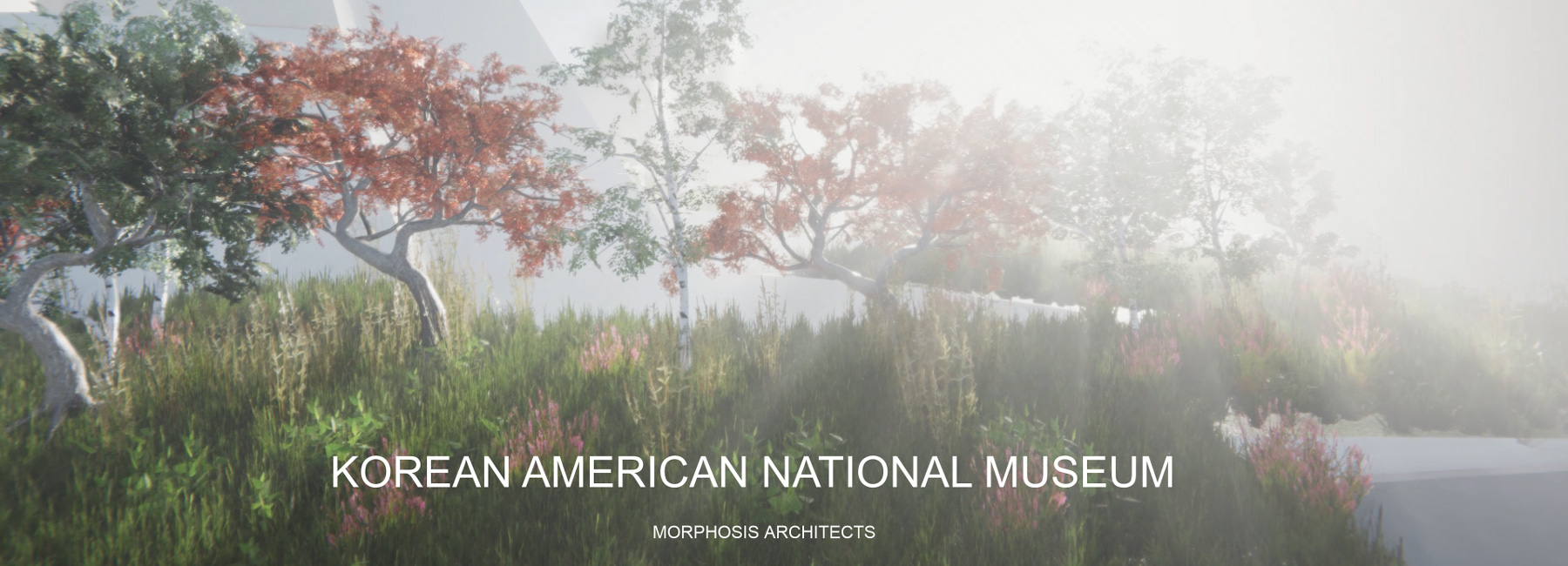
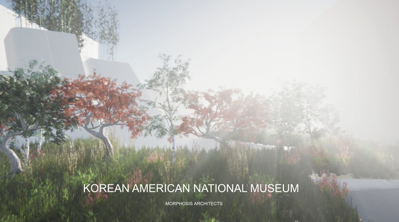
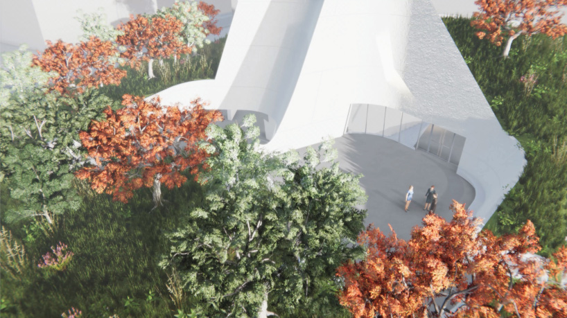
in this article, alessio grancini, advanced tech team member and unity developer at morphosis architects, walks through the steps of how he prepares digital assets for a VR presentation, or ‘experience,’ as they are known in the visualization industry. the tutorial features an experience created during concept design for the korean american national museum in los angeles — previously featured on designboom here. the workflow is oriented towards architects and designers, providing insight into how to leverage and adapt assets created during day-to-day architectural practice for the purpose of immersive experiences. read the complete text from alessio grancini below.
– –
there are several ways to create architectural scenes for virtual reality (VR). selecting the right software and hardware depends on your desired effect and presentation environment — whether the experience will be presented on a mobile device or connected to a computer station — as well as the computing power and resources you have available. that said, it’s important to note that VR scenes do not have to be hyper-realistic! some needs are better served by quick, efficient visualizations; for example, VR ‘sketches’ can be useful for rough-prototyping of different elements or for evaluating spatial relationships and views. morphosis maintains a few different VR platforms and ‘headsets’ for different purposes.
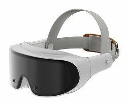
the following tutorial follows the creation of a simple, view-based VR experience, something that we might use to discuss a design concept with a client. the VR experience features stationary, 360-degree views of the building and landscaping. this kind of experience doesn’t include extensive interactive or multiplayer elements, so it is a good visualization to start with if you are just beginning to develop for VR. the software and hardware employed for the experience include the oculus quest headset, along with unity, rhino 6, and grasshopper, along with key plugins described later in this tutorial. on the hardware side, the oculus quest is capable of delivering incredible visuals and experience quality on a lightweight, wireless headset. however, the bonuses of being untethered from the desktop come with compromises in terms of rendering power. the biggest challenge for successfully developing on the quest is carefully managing the 3D geometry for the experience.
while many designers are experienced with using rhino and grasshopper as part of their 3D modeling workflow, they may not necessarily be familiar with unity. unity is a cross-platform game engine used to create two-dimensional, three-dimensional, virtual reality, and augmented reality environments. while most often associated with the world of video game production, many industries can benefit from the capabilities of unity as there are numerous ways to engage and create with the software.
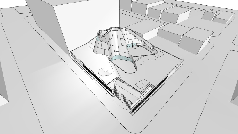
the 3D building model in rhino, before geometry has been optimized
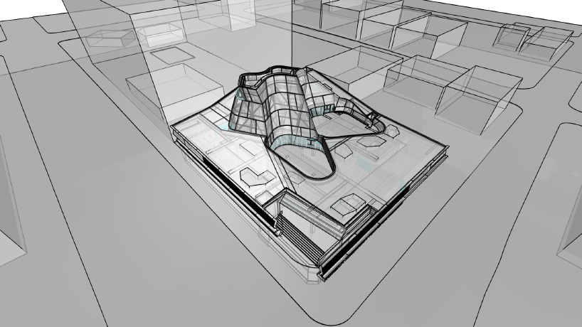
ghosted view of 3D model in rhino showing hidden elements that can be removed for the VR experience
step 1: model preparation and optimization
geometry optimization is crucial to developing ‘smooth’ architectural scenes in VR. not following this vital first step will result in a large amount of lag, in the form of delayed loading of various elements or objects that or flicker or jump as you move. in addition to being frustrating, lag can give people headaches and dizziness when engaging with the scene through a headset. geometry optimization should begin in the native software of your architectural model, before you even open unity or your preferred game engine. optimizing geometry at the beginning will save you a lot of time in the long run. for this experience, we start with a 3D model file created by the architectural design team during the early concept phase of the project. this is a copy of the same 3D model that the team will continue to shape and develop throughout the design process.
the ultimate goal of optimization is to simplify the geometry before introducing it to the game engine, mainly by reducing the number of polygon faces in the 3D mesh. this means that less processing power will be required to render the experience at the end.
the model can be ‘optimized’ in several ways, some manual and others automated.
remove hidden elements
one of the initial steps you can take is to remove excess elements that are irrelevant to the visualization. this requires having a plan for the narrative and scenes that you want to express in the visualization. keep in mind that not all components of a building are visible to the regular visitor; things that are usually hidden, like the HVAC system, structural beams, cabling and so forth can be removed from the model, if they aren’t the focus of the visualization. this simple move can go a long way towards reducing the complexity of the model.
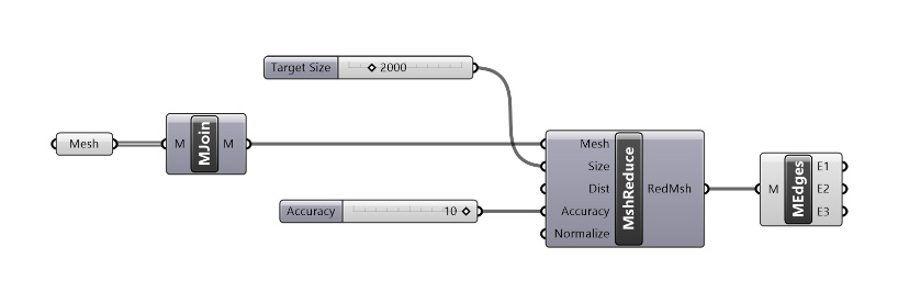
grasshopper visual script including lunchbox plugin components, for reducing polygon count
break into chunks
another way to reduce the amount of polygons is to consider whether your experience can be subdivided into separate scenes. for larger or more complex 3D models with polygon face counts that exceed 100,000, it may be necessary to break the model into ‘chunks’ of the building, such as the entrance and lobby or a specific interior space, and render these chunks separately in the game engine. in the experience, each scene would involve only the chunk of the model being represented at that time; when the viewer changes scene, they are also changing to a different chunk of the model. this can save significant rendering resources, but it also requires careful consideration of the transition experience between different scenes.
merging and optimizing meshes
automated polygon reduction tools work on single mesh layers to reduce the amount of polygon faces in that mesh. so, before we can introduce these tools to our model, we need to transform the geometry in our model from NURBS to meshes, and then join related meshes using grasshopper native ‘join’ function. when merging meshes, it is important to think ahead about how you plan to use the model. for example, you may want to join meshes that will share the same material type, so later you can easily assign a material in unity. you would not want to join meshes that do not share a material, because you will need to separate them again later to assign them their respective materials.
once similar meshes have been joined, you can pipe your resulting mesh into a polygon-reduction tool. there are several tools that can reduce meshed, but the most effective I’ve found is the very useful grasshopper plugin by nathan miller called LunchBox.
LunchBox is a plugin that includes of collection of computational design tools for grasshopper and dynamo. most important for our purposes, the plugin features component nodes for managing data and geometry for activities such as generative form making, paneling, rationalization, and interoperability.
we will utilize the ‘reduce mesh’ function, choosing as our parameters either a target polygon count, or a target percentage of polygon reduction relative to the beginning number of polygons in our mesh.
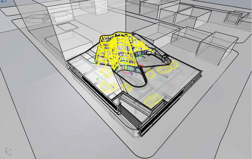
ghosted view of 3D model in rhino with hidden elements selected — these hidden elements can be removed for the VR experience
as a result of this merge-and-reduce operation, our model has been reduced from more than 100 layers to no more than 15-20 mesh layers, comprising altogether only 30,000 triangular polygon faces. considering the original geometry has over 1.5 million polygon faces, this represents a 98% decrease of all polygons in the model — a huge reduction!
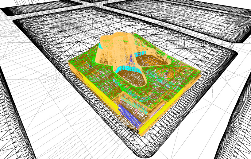
the 3D model in rhino in wireframe mode, after conversion to mesh but before geometry is optimized
screen capture from the VR experience for the korean american national museum, produced in unity
a good rule-of-thumb is to keep the number of polygon faces in a model below 50,000. this can be a troublesome task if your model has very complex surfaces. avoid importing any surface pattern that is too complex, as these can be recreated more efficiently later using unity’s texture mapping feature. when a complex pattern on any surface exceeds 10,000 triangular polygons, it is usually better to use the texture mapping strategy.
there are some precautions and troubleshooting tactics you should keep in mind when optimizing surfaces. LunchBox’s automatic subdivision of mesh edges, vertices, and faces does not always produce the expected or desired result. sometimes a mesh ‘resists’ being compressed, perhaps because of its complex nature or because it has inherited various properties from the software in which the mesh was created. when this happens, the geometry may need to be rebuilt, which will extend and complicate your workflow.
a good workaround for this problem, is to make sure that you are joining elements that are similar in properties, shape, and curvature — and thus polygon count — to each other before mesh-reducing them through LunchBox. sometimes if a joined mesh layer contains elements with radically different geometry, the elements that are simpler, with lower overall polygon counts, will become distorted when subjected to a mesh-reduce operation.
distortions of meshes are not always a bad or accidental thing. anyone whose played a videogame has probably noticed how sometimes the gaming environment contains faceted, ‘low-res,’ and pixelated surfaces. this distortion may be a mistake, but it also may have been a deliberate choice by the game creator, who is constantly weighing which parts of the environment are a priority for rendering. maybe the part of the environment that is distorting is not as significant to the narrative of the gameplay as other parts of the environment, so it is more ‘optimized,’ and does not receive the same degree of rendering power. distortions therefore sometimes serve to direct gamers’ attention to the important aspect of their surroundings.
for architectural visualizations, we have a slightly trickier task, as compared to videogames we are so focused on the presentation of the built environment that it is difficult to de-prioritize some aspects of that environment in order to allocate rendering power. we therefore are usually aiming towards a minimal distortion of all geometry — all meshes should read as smooth, closed, planar surfaces. we can also mitigate distortion with post-processing effects in unity (such as ‘bloom,’ ‘depth of field,’ and ‘antialiasing’), which can help reduce the sensation of scattered or disjointed geometry. for more information regarding the concept of post-processing, check out the unity documentation on this topic.
one final note on reducing polygons — stairs and facades in architecture are usually the elements with the highest polygon count. if we need to temporarily hide or remove elements in the experience in order to optimize rendering power, these should be the first elements to consider.
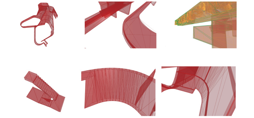
depending on their complexity, curves and elements will be treated differently by the polygon reduction operation. strategically joining meshes offers some degree of control over results
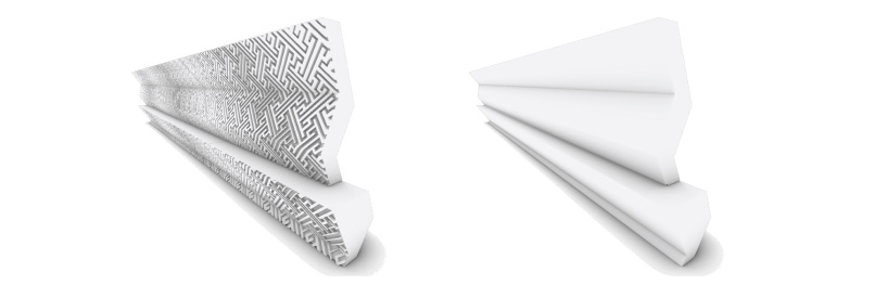
comparison of an asset with a complex surface pattern before and after optimization. the 3D pattern will be remapped on the flat surface as a texture in unity
step 2: setting up the unity and oculus quest environment
beyond rhino and grasshopper, the specific software and packages used for this experience are unity 2019.3 with the universal render pipeline and the unity packages ‘oculus integration’ from the unity asset store and ‘oculus android’ from the unity package manager. after installing these packages, we are ready import our model and start the development of the VR scene.
after your model is optimized following the above suggestions, export it from rhino as an ‘FBX’ file, with the extension ‘.fbx,’ using the default settings. FBX is a middleware file format for transferring assets between CAD programs and gaming engines.
unity offers various templates to select from when beginning a new project. these templates are defined by the rendering performance needed for the experience and the device the experience will be deployed on. in this example, we will be using the universal render pipeline template, which provides a series of pre-built tools for creating experiences for devices such as smart phones and headsets, including the oculus quest.
though unity is a game engine originating in videogame development, its interface is very architect/designer-friendly. like most CAD software, unity’s interface contains a viewport where geometry is manipulated and observed by the user, and a layer tab where geometry is organized and classified. the major difference between unity and most traditional CAD software is the ability to assign interaction and behavior to geometry, as well as of course the possibility to experience the space by pressing play. for further information about how to get started with unity, you can reference unity’s introductory tutorials and documentation on their website.
testing tracking and optimization
once we have imported our model and selected the universal render pipeline template, we should test the tracking and optimization of our model. this is a two-step process; first, we should test-build a basic hand-tracking scene to make sure our set up is working. this is accomplished by selecting ‘android’ as our platform from within the build settings window and clicking build button. the hand-tracking scene is an empty scene containing two prefabricated components derived from the oculus unity SDK: the OVRCamera rig, and hands; use it to ensure that your hands are properly tracking within unity. you can troubleshoot using this guide, which provides an in-depth explanation of the templates included in the oculus unity integration.
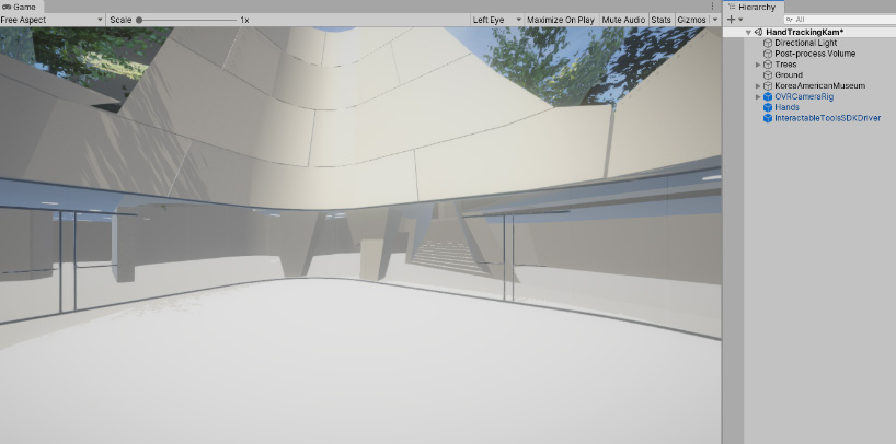
the optimized model imported in unity
after ensuring your hand-tracking sets up successfully inside the blank template scene, we can begin testing our own model by dragging our file into the scene hierarchy panel. beyond simply assessing the smoothness of the viewing experience while in the headset, we can also analyze the performance and optimization of our model by referencing the statistics window within the unity editor, which keeps track of tasks running in the game engine while the scene is being tested. unity also offers a more precise reading of performance through the built-in profiler window. one of the key parameters to watch is the framerate of the experience; the oculus quest borderline frame rate is 72 frames-per-second to ensure a scene runs correctly. for more on testing and performance analysis for oculus quest, refer to the product’s documentation for developing with unity.
if the scene works smoothly, it’s time to start customizing materials and adding entourage and other details to the model to render the desired atmosphere. a third-party package for unity that is extremely useful for this step is ‘substance source,’ available in the unity asset store. substance source provides a range of high-quality textures and surfaces.
some of our imported model assets may have already had materials assigned to them in from their native CAD platform. these should be converted to match the unity render pipeline format, using the material conversion option within the render pipelines settings.
scenes can be enhanced with texture-mapped materials and post-processing, to add details and ambience
going further: switching views
you might want to add the ability to switch between different scenes or views in your experience. for further information on including different scenes in your experience, see documentation on how to manage scenes in unity.
for this experience, we wanted view-switching to be accomplished with an intuitive hand gesture, in this case, a pinching motion. the interaction is enabled by a third-party imported package, named ‘InteractableToolsSDKDriver,’ which uses the oculus quest’s integrated cameras to sense the viewer’s hand motions in front of the headset, and then transposes them into the virtual environment to interact with scene.
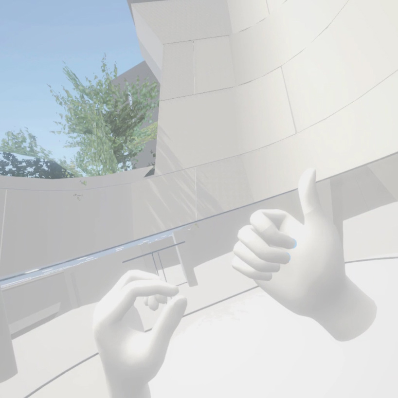
viewers enter the experience at this initial perspective. the hands in the scene correspond with the location of the viewer’s hands in front of the headset
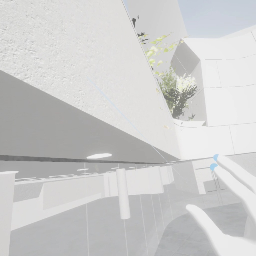
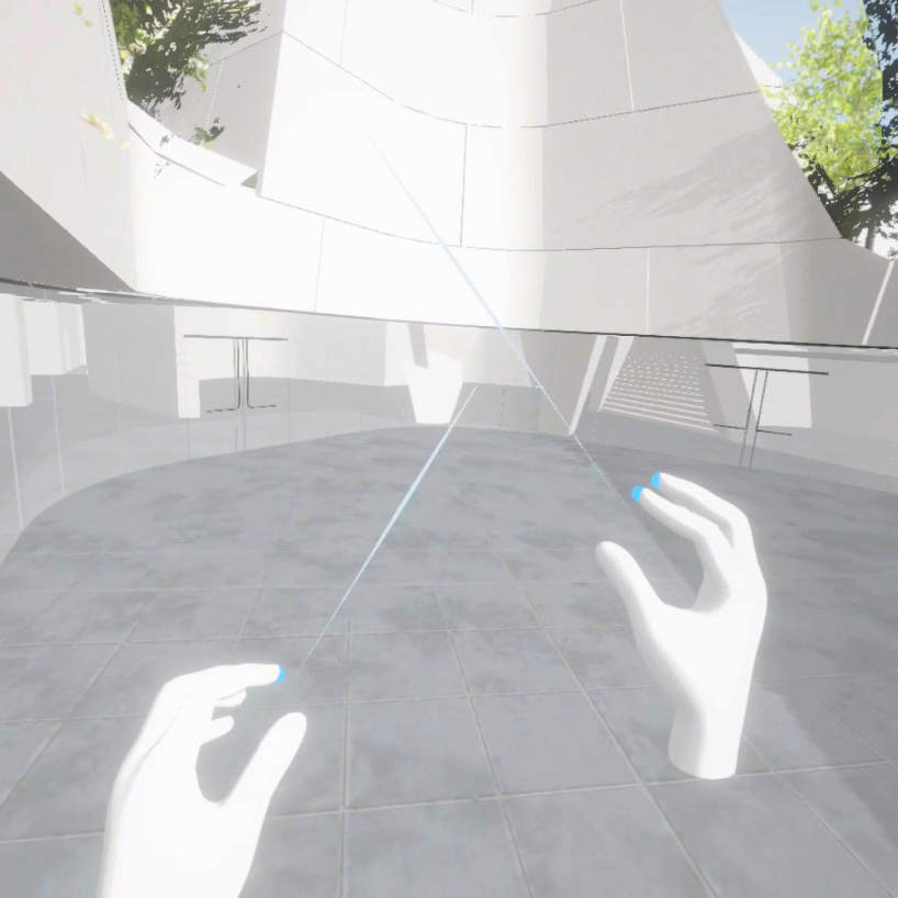
the viewer transitions to the second view by making a pinching gesture in front of the headset
some scripting abilities are required to introduce interactions like this into your experience. since this article is focused on optimization, rather than scripting, we don’t have space to go over the entire code for the hand-tracking interaction. the oculus developer documentation for hand tracking is a great resource for learning to code interaction in to your experience. or, feel free to contact the author of the article directly for tips and guidance.
screen capture from the VR experience for the korean american national museum, produced in unity
final thoughts
the evolution of immersive technologies means that the opportunities for VR to impact architecture are expanding, and not just in the final presentation stage of a project. the unique experiential possibilities of immersive realities — especially considering the integration of interactive gestures and body movements in virtual space — represent an exciting territory for designers, offering new ways to understand projects still under development. there are also myriad ways that architects, trained in understanding and conceptualizing the design of spaces, can contribute to and influence the emerging world of immersive media — designing virtual spaces for artists, for videogames, for virtual meeting rooms and so forth. this tutorial hopefully demonstrated that this integration can be straightforward, built from the models and processes architects and designers already use on a day-to-day basis.
if you have any questions or comments, feel free to contact the author at [email protected].
morphosis architects / thom mayne (32)
 Jun 29, 2023
 Jan 14, 2023
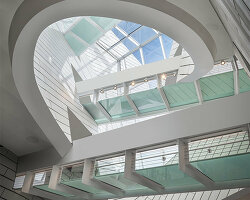 Sep 29, 2022
 Jun 04, 2021
 Jan 27, 2021
virtual and augmented reality (200)
 May 21, 2024
 May 09, 2024
 Apr 11, 2024
 Mar 03, 2024
PRODUCT LIBRARY
 Jul 15, 2024
 Jul 09, 2024
 Jul 09, 2024
 Jun 20, 2024